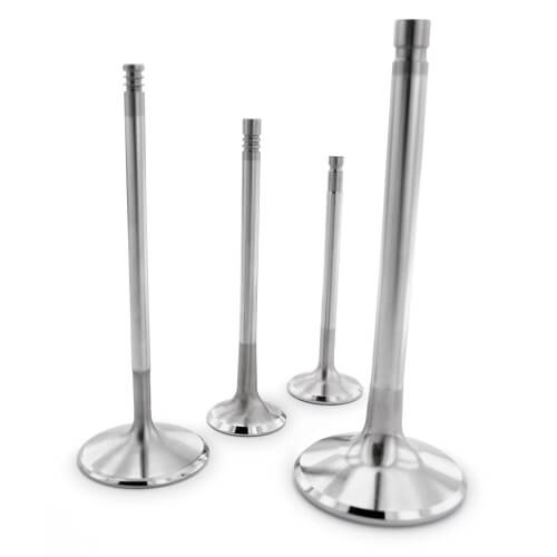
Car Engine Valves Materials
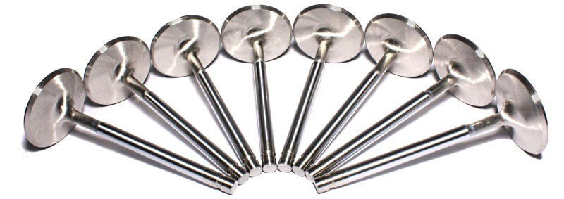
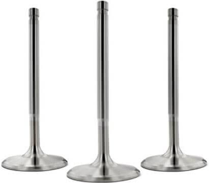
Most stock intake valves are made of EN52 steel while most stock exhaust valves are made of more wear resistant and stronger 21/4N Austenitic stainless steel.
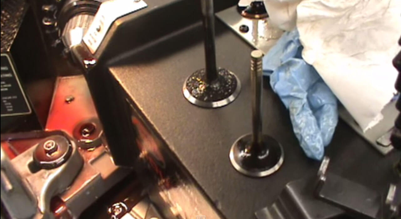
If you're building a modified street car, the stock valve material will be perfect, as long as the exhaust valves are made of 1/4N Austenitic stainless steel; however, if you're building a modified race car, it would be better to replace the stock intake valves with stainless steel valves, which are more wear resistant. As for the exhaust valves, you can easily verify whether they are made of 21/4N Austenitic stainless steel or EN52 steel as 21/4N Austenitic stainless steel is non-magnetic while EN52 steel is magnetic. So, if a magnet sticks to your exhaust valve head, it's EN52 steel. Some manufacturers use a bi-metal construction, with an EN52 steel car engine valve stem micro welded to a 21/4N Austenitic stainless steel valve head; so check the valve head, not the valve stem.
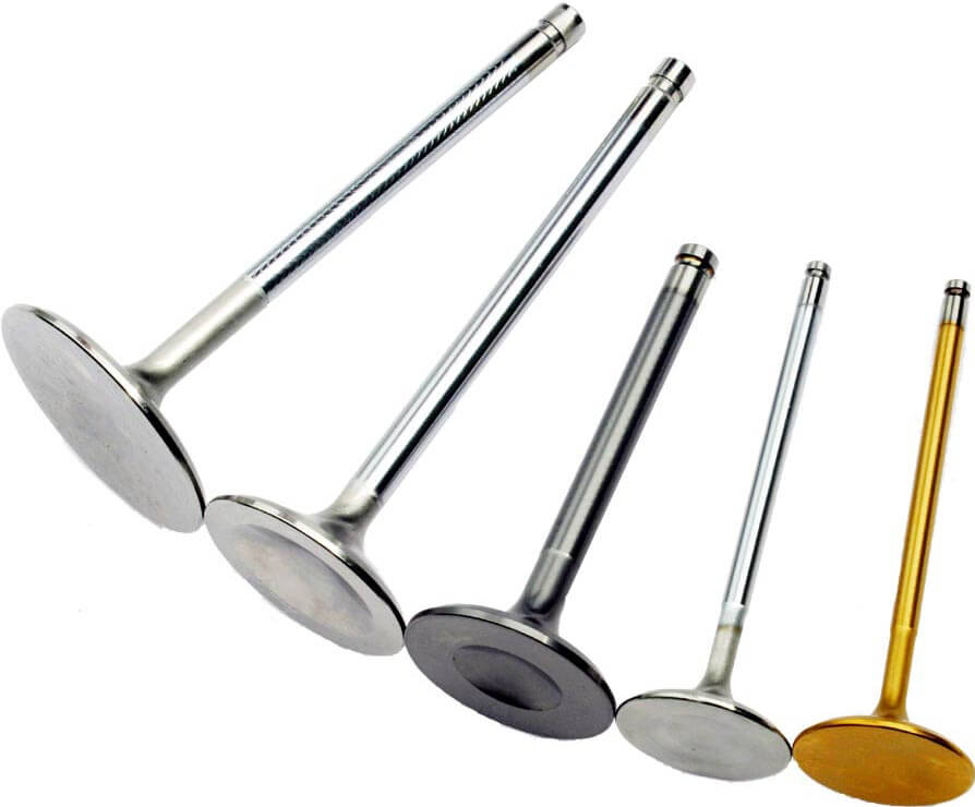
Bigger Valves
Installing bigger intake and exhaust valves may be a good idea for vehicle's performance increase, though there are several things you need to take into account when deciding on bigger valves. The most obvious is that you need sufficient space in the combustion chamber for bigger valves. However, the valve head should be at least 2 mm from the combustion chamber and cylinder wall.Also, if you fit bigger valves, you'll need to open up the ports, which means you'll need to do more cylinder head porting to achieve the full power benefit of fitting bigger valves. But this also means that you'll have reduced the mean gas velocity at low RPM as bigger ports have lower mean gas velocity at low RPM. This translates into less bottom end power, especially on small bore engines.
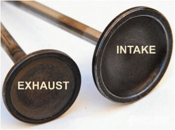
It's not necessary to fit bigger exhaust valves on a naturally aspirated engine, even if it's on a heavily modified race car. This is because of the large pressure differential in the cylinder and the exhaust header. The pressure in the cylinder during the exhaust stroke, when the exhaust valve opens is usually five times higher than the pressure in the exhaust header. Air flows from a high pressure area to a low pressure area until equilibrium is reached; therefore the exhaust gasses are literally sucked out of the cylinder. The movement of the exhaust gasses is aided by the upward movement of the piston, which keeps the pressure in the cylinder while forcing even more exhaust gasses out through the exhaust valve. This also explains why the intake valve is bigger than the exhaust valve.
Qick Exhaust Valves
Commonly referred to as QEV, the purpose of Quick Exhaust Valve is to increase the cycle speed of a cylinder. Depending upon your actuation requirements, installing QEV at the blind end or rod end of your cylinder will result in rapid retraction or rapid extension. When pressure is removed from the Quick Exhaust Valve's input port, back flow at the output port will unseat the valve's internal components, relieving large amounts of flow in a minimal amount of time.
Valve Timing
As with ignition timing, accurate valve timing, or cam timing as some people refer to it, is critical for achieving maximum horse power delivery from your engine.
1. The first thing you need to accurately set your cam timing is a timing degree wheel, or a cam timing disc, that you can get from your camshaft manufacturer. You also need a dial gauge with a magnetic stand to find true top dead center (TDC) of the no. 1 cylinder and the correct valve lift, and an adjustable vernier gear. It is easiest to set the cam timing before the cylinder head is fitted to the engine. You need to accurately determine TDC using the dial gauge and accurately mark TDC on the crankshaft pulley. Usually, the car manufacturer would mark TDC on the crankshaft pulley, but you should verify that it is marked accurately as if it is even just a few degrees out, it can have a significant effect on power delivery. Accurately marking TDC on the crankshaft pulley will also be helpful when want to check or adjust the cam timing at a later stage, with the engine fully assembled and fitted.
2. The next step is to bolt the cam timing degree wheel to the crankshaft, fit a temporary pointer to the engine block and set the pointer to TDC or 0° on the cam timing degree wheel. Then fit the cylinder head and install the camshaft, or camshafts if it's a twin-cam cylinder head. The engine should be at TDC and at the end of the compression stroke on the no. 1 cylinder, so the camshafts should be installed with the intake and exhaust valves of the no. 1 cylinder closed.
3. The camshaft manufacturer or grinder will provide you with a specified engine valve lift and the point at which that valve lift for the intake valves and the exhaust valves should be achieved. This may be for full-lift, or a specified amount of valve lift with the valve opening. Also, the point at which the valve lift is achieved is measured in degrees of crankshaft rotation, which is why we bolted the timing degree wheel to the crankshaft. Our next step is to attach the dial gauge to the cylinder head, with the stylus on the intake valve of the no. 1 cylinder and zero the dial gauge.
4. Now rotate the crankshaft to the specified point at which the specified valve lift should be achieved and read the amount of valve lift off the dial gauge. If it is not the same as the valve lift specified by the manufacturer, then free up the vernier gear and turn the camshaft until the correct valve height is achieved. Take care not to let the valves hit the crown of the piston while you're doing this adjustment as the valves could bend quite easily.
5. With the specified valve lift of the intake valve occurring at the specified degrees of crankshaft rotation, tighten up the vernier gear. Your intake valve timing is now set. On a single-cam cylinder head you just need to verify that the exhaust valve also reaches the specified valve lift at the specified point. But on a twin-cam cylinder head you will need to set your exhaust valve timing by repeat this process for the exhaust valve of the no. 1 cylinder.